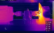
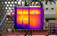
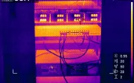
Thermal imaging test allows to perform measurements of temperature distribution in the tested object in the form of a color map obtained from the image of a thermal imaging camera. It is a modern and accurate measurement method, enabling the location of hot spots, detection of faults manifested by the release of excess heat or, finally, non-contact and non-invasive temperature measurement in particularly dangerous conditions and in places difficult to access for contact methods (measurement using thermometers).
The Institute performs thermal imaging measurements in the field of:
- machines and transformers,
- mechatronic systems and industrial automation systems,
- electrical installations.
The measurement results are presented in the form of color maps or videos.
Offer of measurements and tests performed in the EMClab LUT laboratory
- Harmonic emissions in the supply current,
- Conducted Emissions (9 kHz - 30 MHz),
- Radiated Emissions (30 MHz - 1 GHz),
- Study of voltage changes, voltage fluctuations and light flicker,
- Immunity to conducted radio disturbances,
- Resistance to electromagnetic field GTEM,
- ESD resistance (electrostatic discharge) ,
- BURST resistance (series of electrical transients) ,
- SURGE resistance (strokes) ,
- Resistance to dips, interruptions, voltage changes,
- Magnetic field resistance,
- Development of research reports,
- Design research
Equipment gathered in the EMC Laboratory and its research capabilities
1. Generator BESTPlus (Schaffner)
For performing EMC immunity tests , including:
- Fast impulse disturbances - BURST
- Impulse surge interference - SURGE
- Static electricity discharges - ESD
- Dynamic changes in the value of the supply voltage - PQT
Basic technical data:
- Power source DUT (80 –260) Vrms, 50/60 Hz, 16 Arms (0 –65) Vdc, 10 Adc
- BURST (0,2 – 2,2) kV / 1kW lub (0,1 – 1,1) kV / 50W , frequency (1– 100) kHz, okres (0,1 – 99) s, number of impulses (1 – 75)
- SURGE (0,2 – 2,2) kV / no load, (0,1 – 1,1) kA / short circuit
- ESD air (0,2 – 8,8) kV, contact (0,2 – 6,6) kV
BURST
High-voltage, fast-rise bursts (BURST) simulating the noise produced by inductively loaded electromechanical switches.
These disturbances can be coupled:
- directly through the supply network, as a result of connecting a device generating interference to this network
- by capacitive coupling from a jamming device or power line to nearby devices.
The Best Plus generator allows you to carry out tests by both coupling methods (galvanically into the power cords and using capacitive coupling clamps).
SURGE
Impact tests (SURGE) simulate interference with high-energy pulses, e.g. as a result of lightning discharges into the power grid or by shutting down heavy loads. Test surge pulses can be inserted into the power supply lines (galvanically) or into other circuits (by capacitive coupling).
ESD
Electrostatic Discharge (ESD) tests simulate high-voltage pulses that can occur as a result of a contact discharge (a charged person directly touches an object) or as a result of an air discharge (arc through air). The BESTPlus generator is equipped with an ESD gun with appropriate testing fingers for both types of discharges.
PQT
Power Quality Testing (PQT) simulates fluctuations and power outages in the mains.
2. EMI Precompliance Test System - Hewlett-Packard HP 84110EM apparatus
The HP 84110EM Measurement Kit is used to test (in the pre-compliance and diagnostic categories) the emission of conducted and radiated interference. The kit includes the following items:
- Spectrum analyser (HP 8591EM), 9kHz - 1,8GHz
- complete measurement system EMC (span and CISPR16 bandwidth)
- displays two limits(określające poziom dopuszczalnych zakłóceń)
- korekcja dla urządzeń pośredniczących (np. antena, LISN, wzmacniacz, sonda pola, itp.)
- pomiar amplitud peak, quasi-peak, average (kursory oraz zoom)
- wewnętrzna lista może zawierać do 239 pomiarów
- Tracking generator (in spectrum analyser housing)
- Artificial network - LISN (HP 11967D)
- Preamplifier (HP 8447F)
- Dynamic state limiter (HP 11947)
- Near-field probe (HP 11940A), 30MHz - 1GHz
- Near-field probe (HP 11941A), 9kHz - 30MHz
- Dual cone antenna (HP 11955A), 30MHz - 300MHz
- Rod antenna (HP 11956A), 200MHz - 1GHz
- Antenna stand (HP 11968C)
3. Precise analyser LCR - HP 4284A, Hewlett-Packard
It is used to measure the following parameters:
Z , Y , q , L , C , R , G , D , Q , RS , RP , X , B
Technical data:
- test signal frequency 20Hz - 1MHz, ± 0,01% (8610 wybieralnych częstotliwości)
- measuring ranges: 0,01nH - 100kH, 0,01fF - 10F, 0,01mW - 100MW
- measuring accuracy ± 0,05%
- Poziomy sygnałów testowych (rms): 5mV -20V, 50m A - 200mA
4. AC Power Source / Analyzer - HP 6813B, Hewlett-Packard
To perform emissivity and immunity tests for low-frequency conducted interference, including:
- Tests emissivity - emissions of quasi-stationery current harmonics, fluctuating current harmonics, and voltage fluctuations and flicker.
- Tests immunity - immunity to voltage dips, interruptions and fluctuations, and frequency variations.
- Tests immunity - immunity to harmonics, interharmonics, and mains signalling voltages.
Basic specifications:
- 1-phase power supply, 1750VA, 300Vrms, 13Arms, 80Apeak, ± 425Vdc, 10Adc
- Output frequency: 45Hz - 1kHz or dc
- Programmable: voltage, frequency, phase, output impedance, harmonic level, power supply fault sequence simulation
- Measurements (16-bit resolution): Vrms, Irms, Ipeak, frequency, phase, apparent power, reactive power active power, power factor (PF), harmonic content (THD)
- Voltage and current harmonic analysis (up to 50th harmonic)
5. Harmonic / Power Analyzer - HA 2000, AMPROBE
A small, lightweight, portable instrument for the diagnosis of low-voltage mains circuits. Allows measurement and analysis of currents, voltages, power and harmonic content.
Basic technical data:
- Voltage range (AC/DC) (1 - 600) Vrms (1000Vpeak)
- Current range (AC) (1 - 1000) Arms
- Power range (0 - 600) kW
- Frequency (40 - 65) Hz
- Harmonic analysis in current and voltage: up to the 19th harmonic (on the display) or up to the 31st harmonic (after downloading the data to a PC) and determination of the THD coefficient
- Power measurements: active power, reactive power, apparent power, distortion power, power factor (PF, dPF)
- Memory for recording of 21 measurements
- PC-compatible download of additional quantities: Crest factor, Form factor and Transformer overload factor K (K factor)
6. Oscilloscope – TDS 680C, Tektronix
Enables the measurement and comprehensive analysis (time domain and frequency domain) of electromagnetic interference in the frequency band up to 1 GHz.
Basic technical data:
- Number of channels 2 + 2
- Analogue bandwidth 1 GHz
- Sampling rate 5 GS/s (all channels simultaneously)
- Maximum recording length 15,000 points (per channel)
- Vertical resolution 1 mV/div - 10 V/div
- Time base 200 ps/div - 10 s/div
- Timing accuracy < 50 ps at 5 GS/s
- Switchable input 50 W / 1 MW , AC / DC
- Analysis and processing:
- Time domain processing - sin(x)/x or linear interpolation, averaging, Auto Setup,
- Operations - FFT, integration, differentiation, addition, subtraction, multiplication, inversion,
- Comparison of waveforms with reference waveform,
- Histograms - allow statistical distribution analysis,
- ZOOM function with double window.
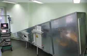
7. GTEM 1000 chamber, TESEQ
The GTEM chamber provides the possibility to perform interference emission measurements over a very wide frequency band and RF immunity tests. The GTEM chamber consists of a shielded enclosure ensuring that tests can be performed in an urban environment (full of radio interference), while at the same time the shielding prevents radio emissions from escaping to the outside.
Basic technical data:
- Operating frequency: DC to 20 GHz
- Measuring area according to standard: 0.6 x 0.6 x 0.3 m
- Maximum measurement area (engineering measurement): 0.74 x 0.74 x 0.66 m
- Chamber impedance 50 ohm
- EUT panel - 2 x 16 A signal filter, 1 power socket, main switch, earth leakage circuit breaker, light switch, earth leakage protections
- Signal panel - 3 x N-type connector and fibre-optic conduit type "tube" 3/4"
- Monitoring function of the device under test inside the chamber (optical fibre)
- Maximum input power: 1000W
Laboratorium NanoLab oferuje kompleksowe badania mikroskopowe próbek przewodzących i nieprzewodzących w szerokim zakresie powiększeń – od skali makro do nano. Analizy przeprowadzane są z wykorzystaniem mikroskopii elektronowej (SEM) oraz mikroskopii sił atomowych (AFM).
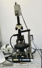
Jako badanie wstępne, w ramach oceny parametrów badawczych, stosowana jest także mikroskopia świetlna.
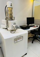
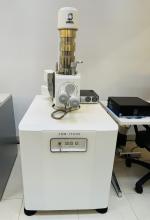
Mikroskopia skaningowa elektronowa (SEM)
Laboratorium dysponuje nowoczesnym mikroskopem skaningowym JEOL JSM–IT200 In-Touch-Scope, który umożliwia badanie różnorodnych materiałów dzięki:
- Działu elektronowemu z katodą wolframową, zapewniającemu jasną i koherentną wiązkę elektronową bez konieczności stosowania wysokich prądów emisji.
- Szerokiemu zakresowi napięcia przyspieszającego (od 500 V do 20 kV).
Możliwości badawcze
- Detektor elektronów wtórnych (SE) – odwzorowanie topografii preparatu, analiza próbek w stanie natywnym.
- Detektor elektronów wstecznie rozproszonych (BSE) – analiza składu materiałowego po odwrotnym spolaryzowaniu siatki detektora SE.
- Mikroanaliza rentgenowska (EDS) – analiza struktury i składu chemicznego próbek na poziomie molekularnym.
- Możliwość badania materiałów nieprzewodzących – próbki mogą zostać pokryte materiałem przewodzącym za pomocą napylarki sputteringowej.
Cennik SEM
- Mikroanaliza powierzchni pojedynczej próbki (bez przygotowania) – 500 zł netto
- Z przygotowaniem próbki – 550 zł netto
- Dodatkowa analiza EDS – 650 zł netto
(Ceny zawierają koszt pracy operatora: 250 zł netto dla próbki bez przygotowania, 350 zł netto dla próbki wymagającej przygotowania.)
Mikroskopia sił atomowych (AFM)
Laboratorium dysponuje mikroskopem NT-MDT Solver Pro AFM, który umożliwia:
- Skanowanie powierzchni w zakresie 50x50 mm
- Badanie obiektów o wysokości do 15 mm
- Obserwację w trybach „semi kontakt” oraz „kontakt”
- Analizę mikro- i nanostruktur materiałów organicznych i nieorganicznych z nanometrową rozdzielczością
Cennik AFM
- Analiza jednej próbki wraz z przygotowaniem – 1000 zł brutto